I2C, also referred to as IIC, stands for Inter-Integrated Circuit. It’s a serial communication protocol created by Philips Semiconductor (now NXP). Many microcontroller implement peripherals that are compatible with I2C, which are often called TWI or 2-wire serial interface. For the most part, TWI and I2C are the same thing, so I’ll be referring to them as I2C for this discussion. Think of TWI as the off-brand or generic version of I2C.
Protocol
I2C is a serial, synchronous protocol like SPI. Just like SPI, it has a master that controls the bus, and slaves that are part of that bus. The I2C protocol only has two signals: SDA for data, and SCL for the clock. This may come as a surprise if you read my last post; SPI needs CS, MOSI, MISO and SCK; why does I2C only need two? How can meaningful communication occur with so few signals? The answer: while SPI has dedicated signals for different functions (CS to select a slave, MOSI to send data, MISO to receive data), I2C has its few signals fulfill multiple functions.

From Sparkfun
I’ve found the best way to understand I2C is by comparing it to SPI. Let’s do that:
- Framing a transfer: how does a master on the SPI bus begin a data transfer with a slave? Well the CS signal of that slave is driven low. On the other hand, when a data transfer is ended, CS is driven high. How does I2C do it? Well, since I2C does’t have CS signals, it uses SDA and SCL to do the same thing. SDA, ordinarily, can only change value when SCL is low. However, if a falling edge occurs on SDA while SCL is high, then that means a transfer is beginning. If SCL has a rising edge when SCL is high, then that means a transfer has ended. As you can see, the function of the CS signal has been fulfilled by SDA and SCL.
- Selecting a slave: how does a master on the SPI bus select what slave to send data to, and receive data from? Well SPI does this by giving each slave on the bus their own unique CS signal. These signals are usually driven high, and when a device is selected for the transfer, only that device’s CS is driven low. How does I2C do it? Well, since I2C doesn’t have multiple CS signals, it uses addressing instead. Each device that uses I2C has an address burned into its silicon by the chip manufacturer. The first byte that the master transmits contains a 7 bit address; all the slaves listen to this first byte and compare the it against their own address. If the address the master send out matches its own address, then the slave continues listening. If the address does not match, the slave stops listening.
- Sending and receiving data: how does a master on the SPI bus send and receive data from its slaves? It uses MOSI and MISO; by having two different signals, the master can output on one and receive on the other. How does I2C do it? Well, since I2C doesn’t have a wire dedicated for the master to output on, and another for the slave to output on, SDA has to pull double-duty. When the master first begins I2C communication, along with sending out a 7 bit address, the master sends out a bit that is high or low. If this bit is low, then the transfer is a write, which means the master is sending data to the slave. If this bit is high, however, then the transfer is a read, which means the slave is sending data to the master. If that’s the case, then the slave takes control of SDA and starts outputting data onto it, which the master will then read. This read/write bit, as it’s called, determines whether SDA is used to send data to the slave, or send data from the master, which effectively allows it to take the role of both MOSI and MISO.
As you can see, I2C can frame a transaction, select a slave, and send data both ways using only SCL and SDA, while SPI needs four signals. There are two nuances that I would like to point out.
Firstly, if SDA is an input or an output for the master, and it’s an input or output for the slaves, then isn’t there a risk of output contention? For example, if the master tries to drive a low onto SDA, and a slave tries to drive a high, then that could damage the devices on the bus, right? The answer is no! All devices on the bus drive SCL and SDA using open-collector drivers. This means that devices can only pull SCL and SDA low, but not high. In order to “drive” a high, the devices simply stop trying to drive SCL and SDA. SCL and SDA need to have pull-up resistors on them; that’s why when no device is trying to drive a low, the signals return to being high. If one device tries to drive high, and the other tries to drive low, no output contention occurs because the device trying to drive high doesn’t actually do anything, which means the signal is driven low without any contention.
Secondly, if the master is performing a read, which means the slave controls SDA, then how does the master get control of SDA again? It would be a problem if the master is trying to output data onto SDA, but the slave did the same thing, right? The answer is by using acknowledge bits. After every 8 bits, there is an acknowledge bit. If the acknowledge bit is high, then there was no acknowledgement. If the acknowledge bit is low, then there was an acknowledgment. If a master is writing to a slave, then the master outputs 8 bits of data, and then the slave needs to acknowledge the master. If the master is reading from a slave, then the slave outputs 8 bits of data, and then the master acknowledges the slave. If the slave is acknowledged, then the slave will continue to control SDA, and continues to output data. However, when the master wants to stop reading from the slave and reclaim control of SDA, the master will not acknowledge the slave. The slave, since it wasn’t acknowledged, will stop driving SDA, which will allow the master to select another device.
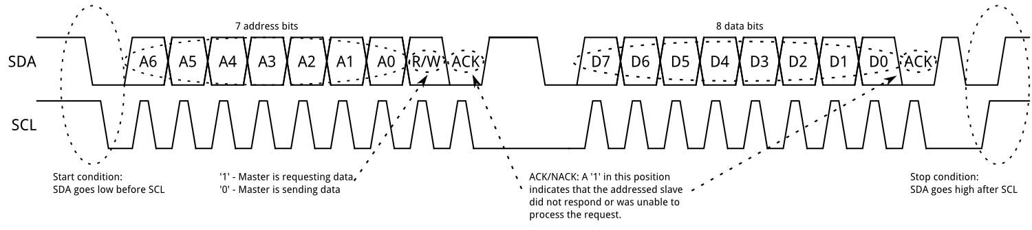
Now that we’ve talked about how I2C compares to SPI, let’s see how I2C actually works. As mentioned, the master begins the I2C transaction by driving SDA low when SCL is still high; this is called a start condition. Then, the master will output a 7 bit address (A6~A0 in the figure above), and then the read/write bit. If there is a slave on the bus that has the 7 bit address output by the master, then that slave will acknowledge the master. If there is no such slave, and the master is not acknowledged, then the master will either try again or abort the transaction.
Assuming the slave has acknowledged the master, the data transfer can begin. If the read/write bit is low, then the master is sending data to the slave, and the slave will listen to the data the master outputs. After the master sends 8 bits of data, the slave will acknowledge the master, and then the master can either continue to send more data, or it can terminate the transfer by sending a stop condition (by letting SDA go high while SCL is also high). If the read/write bit is high, then the master is reading data from the slave, and the slave will start outputting data onto SDA. After the slave sends 8 bits of data to the master, the master can continue to read data by acknowledging the slave, or it can terminate the transaction by not acknowledging the slave.
I2C also supports multi-master configurations. A master can claim the I2C bus by driving a start condition, and then gives up control of the bus by outputting a stop condition. This scenario is useful if you have multiple microcontrollers trying to communicate with devices on the same bus. However, this is outside the scope of this discussion.
One last thing to mention is something called a repeated start. A repeated start condition is the same thing as a start condition. The only reason it is special is because it occurs after a start condition, but before a stop condition. In other words, a repeated start is a start condition that is sent out when a transaction hasn’t actually been terminated by a stop condition, hence its name. It’s typically used to re-select a slave. For example, EEPROM or similar memory chips typically have a pointer register that selects a page or address to read from. In order to read from this memory chip, you would need to do two transaction: the first to write to the pointer register, and then a second to read the data. The full transaction, then would look like this: START – slave address + write – write to pointer register – START – slave address + read – read data – STOP. The second start condition in the previous sentence is the repeated start. If a chip requires a repeated start, then the datasheet for the chip will explain how to use it.
Peripheral

From ATMEGA32U4 datasheet
Above is the hardware in the ATMEGA32U4 for using I2C. The Bus Interface Unit is responsible for reading and writing to SCL and SDA; for example, TWDR is where you put the 7 bit address of the slave you want to address, as well as the data you want to output. If the microcontroller is doing a read, then TWDR will contain the data from the slave. Beside it is the Bit Rate Generator, which determines the frequency of SCL by using a prescaler and counter. The Address Match Unit, which is used when the microcontroller is in slave mode (and will therefore need to listen for its own address) won’t be discussed since the microcontroller will always be in master mode for our purposes.
The control unit is the brains of the operation. It’s main function is to tell the Bus Interface Unit what to do; for example, the Control Unit will tell the Bus Interface Unit to send a start condition, or to send a byte of data, for example. The Control Unit will also contain information about the state of the bus; for example, after a 7 bit address is sent out, the status register will tell you whether the address was acknowledged or not.
The complexity of the I2C protocol is reflected by the complexity of the hardware and the software, as we’ll see below. For our purposes, the microcontroller will operate in Master Transmitter mode, which means the microcontroller is outputting data, and Master Receiver mode, which means the microcontroller is reading data. Let’s look at the two modes below:
Master Transmitter
To send a start condition, write the following to TWCR:

From ATMEGA32U4 datasheet
TWINT should be written 1 to clear the TWINT flag. TWSTA should be written 1 to alert the peripheral that a start condition should be sent out. TWEN should be written 1 to enable the hardware.
Once a START condition has been transmitted, the TWINT flag is set, so the software must wait until this occurs. Then, write the 7 bit address and the read/write bit to TWDR. In order to send the slave address and the read/write bit (read/write bit will be 0 since the master is sending data), write the following to TWCR:

From ATMEGA32U4 datasheet
Clearing the TWINT flag will cause the peripheral to transmit the contents of TWDR. Then, once the address and read/write bit have been sent, the TWINT flag will be set once more, so the software must wait like last time. Next, write the data to send out to TWDR, and then transmit the data by writing to following to TWCR:

From ATMEGA32U4 datasheet
It’s the same operation as the previous step, because really it’s the same operation: shift out what’s in TWDR to the I2C bus. Like before, TWINT flag will be set when transmission has finished, so wait for that before moving on. Now, you can keep repeating this step to shift out more data, or you can end the transmission by sending a stop condition. To do that, write the following to TWCR:

From ATMEGA32U4 datasheet
Here, set TWSTO to tell the peripheral to send a stop condition.
If a repeated start is necessary, then write the following to TWCR:

From ATMEGA32U4 datasheet
You’ll notice it’s the same operation as a start condition, which makes sense since a start condition and repeated start condition are the same thing.
So far we’ve talked about how to tell the peripheral what to do; now we’ll talk about how to read the status of the peripheral, and by extension, the I2C bus. TWSR contains code that the software can use to determine its next course of action:

From ATMEGA32U4 datasheet
For example, after sending a start condition, the software will write to TWDR and then send the 7 bit address + read/write bit. When the TWINT flag is set again, which means that the transmission has finished, the software should read TWSR. If a slave has acknowledged the master, then the status code will be 0x18, and the software should continue with the rest of the operation. If the master was not acknowledged, then the status code will be 0x20. This means that there were no devices on the bus with the specified 7 bit address, which means there’s no point in continuing this transaction, so the software may abort its current transaction.
Likewise, when the master sends out a data byte, it can read TWSR to see if the data byte has been acknowledged. If it has been acknowledged, then the status code will be 0x28, and the software can continue to send more data, or send stop condition. If it hasn’t been acknowledged, then the status code will be 0x30; in this case, the software should abort the transaction.
Master Receiver Mode
The receiver mode is actually very similar to master transmitter mode.
Firstly, send a stop condition:

From ATMEGA32U4 datasheet
Then, wait until TWINT flag is set. Next, write the 7 bit address and the read/write bit to TWDR (read/write bit will be 1 since the master will be performing a read). Then, transmit the contents of TWDR by writing the following to TWCR:

From ATMEGA32U4 datasheet
Once the address has finished sending, the TWINT flag is set again. The software should wait until TWINT flag is set; once it is, TWDR will contain the received data byte. In order to request more data, the above should be sent again and again until enough data has been received. In order to tell the slave to stop transmitting, on the request for the last byte, the image above should be written to TWCR again, but TWEA should be 0. This will prevent the master from acknowledging the slave, and the slave will stop transmitting.
To finally stop the transaction, send a stop condition (or repeated start condition to start another transaction):

From ATMEGA32U4 datasheet

From ATMEGA32U4 datasheet
As before, you can read TWSR to see what the state of the peripheral and I2C bus are:

From ATMEGA32U4 datasheet
As before, reading the status code can be used by the software to see what to do next.
Software

The constructor is shown above. The bitrate and prescaler are configured so that SCL is driven at 100 kHz. Most devices can support up to 400 kHz, but 100 kHz is the default for my code. Then, the acknowledge is setup. The microcontroller’s address and address mask are set up as well, though they’re not used in this application since the microcontroller always operates in master mode.
Before the peripheral is enabled, a timeout is set. This timeout is not part of the peripheral, and is purely software. At several points, the software must wait for the TWINT flag to be set. However, it is possible for TWINT flag to never be set. In this case, the software will wait forever, effectively halting execution. To prevent this, I added a timeout feature; after waiting a certain amount, the software will report that the I2C transaction failed. The code for this is shown below:

The various methods called by the constructor to set up the peripheral are shown below. Per usual, these methods mostly perform bit manipulation on I/O registers:

Before moving onto the juicy code, I’ll show the enums used by HAL_TWI to denote both the status of the peripheral, and any errors that have or haven’t occurred:

TWI_STATUS enums are the ones defined in the datasheet, and are used to see if the I2C bus is behaving as expected. TWI_ERROR enums are reported to whatever is using HAL_TWI, and denote if an error has occurred.

The code above shows sending a start condition. As described previously, TWCR is configured to send a start condition. Then, the software waits for TWINT to be set. Then, TWSR is read to see the status. If a start condition (or repeated start condition) has been transmitted, then the method was a success, and the method returns TWI_NO_ERROR. If a timeout occurred, then the method returns TWI_TIME_OUT. If the start condition wasn’t sent for whatever reason, the method returns TWI_MISC, which means that somehow something went wrong. The last two mean the start condition wasn’t sent, and the transaction failed.

After sending a start condition, the slave address and read/write bit must be sent. The method above does just that. First, the method checks if a start or repeated start has been transmitted. If so, TWDR is updated to contain the 7 bit address and the read/write bit. TWDR is then shifted out onto the bus by updating TWCR. Then, the software waits for TWINT flag to be set. Once the flag is set, the status is checked. If the address is acknowledged, then the method reports success by returning TWI_NO_ERROR. If the address is not acknowledged, the method returns TWI_ADDRESS_NAK. If the status has TWI_NO_INFO, then a timeout has occurred. Lastly, if something else went run, the method returns TWI_MISC. If a start or repeated start wasn’t sent out before this method was called, then the method immediately returns a TWI_NO_START error.

After sending the address (or after sending data), a byte of data can be sent if a write is performed. The code for this is shown above. First, the method checks for proper set-up; if the set-up is wrong, the method returns an error. Otherwise, TWDR is updated with the byte to send, and then TWCR is configured to send the data. Afterwards, the software waits for the TWINT flag. After waiting, the software reports whether the transaction was successful or not.

Like sending data, the code above checks for proper set-up, and then configures TWCR. One point of subtlety, however. TWEA should be 1 if this is not the last byte being read from the slave, and 0 otherwise. Therefore, read_data needs the gen_ACK argument to know if the byte sent by the slave should be acknowledged or not. If the data is received successfully, which the software can determine by checking the status register, then val is updated with the data. Otherwise, the method returns an error.

The code above sends the stop condition. I tried listing all the valid reasons to send a stop condition, like after successfully sending a start condition, or sent data was acknowledged. Whether or not an error occurred, to_return is updated before the stop condition is sent. Then, the stop condition is sent, and to_return is returned.
Examples
I’ve written code for LTC2451. The code to read the ADC reading is shown below:

After setting the peripheral’s clock prescaler and counter to get the correct clock speed, the code sends a start condition, the address + read bit, then reads two bytes from the device, and then sends a stop condition. After each of these steps, the error code is checked to see if an error occurred.

Above is code to write to LTC2451. The code, after configuring the prescaler and counter to get the correct I2C clock speed, sends a start condtion, address + write bit, a byte of data, and then a stop condition. As before, after each of these steps (except for the last one), the returned error is checked to see if an error occurred.
Conclusion
As you’ve seen, I2C is a complex and very useful serial interface. It’s slower and much more complex than SPI, but it can support way more devices, and requires fewer wires. For this reason, I2C is best suited for buses that don’t require high speed, and need to have a myriad of devices on them.
I hope you enjoyed reading about I2C, and how to implement & use it for the ATMEGA32U4!
